

 FR
FRStatic and fatigue tests on an anti-roll bar
As part of a study conducted on behalf of one of our clients, the Railway Test Agency (AEF) had to design a test rig to meet a number of different goals regarding an anti-roll bar.
Description of the part studied
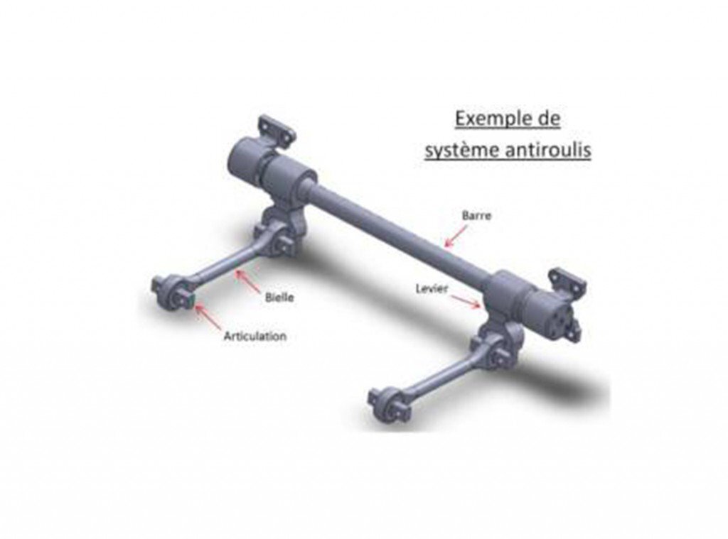
Anti-roll bars are fitted between bogie and vehicle body. Their purpose is to absorb the body roll occurring during curving that would otherwise cause the vehicle to sway from side to side with the attendant discomfort for its passengers.
The principle consists of using a cylindrical steel bar generally mounted on the bogie and connected to the vehicle body by means of two arms or rods, one fitted at either end.
In the event of body roll, torsion in the bar is increased via the rods, which serves to contain the roll. The system acts as an inexpensive stabiliser that has the added benefit of requiring far less maintenance than conventional suspensions.
Customer requirements

As part of a study conducted on behalf of one of our clients, the Railway Test Agency (AEF) had to design a test rig to meet a number of different goals:
- To verify the characteristics of a new type of flexible joint at either end of the anti-roll bar rods (approval of sub-contractor manufactured product).
- To measure the stresses in the rods (checking deformation to confirm the strength factor).
- To study wear at the grooved connection with the levers (investigations) caused by rotation in the bar.
- To confirm the fatigue behaviour of the different components by means of COFREND-certified non-destructive tests (absence of cracks).
Test rig
The first thing to remember is that a test rig, however well-designed, cannot always exactly reproduce the kinematics of a complex component (combination of rotation, linear translation, torsion, etc.) as a result of design features selected to ensure test feasibility in relation to the quality standards expected by the client. It may also be difficult at times to cater to the need for tests to be “representative” in cases where comparisons have to be made with mathematical structure calculations, themselves based on a number of assumptions (simulation of connections, mesh sizes used in calculations, behaviour factors, etc.).

Test rig design and the resulting limitations are aspects that we discuss with our clients before embarking on tests and during the rig design phase using 3D CAD tools.
To reproduce service loads as accurately as possible, a complete anti-roll bar has been developed.
Dynamic forces are applied on both sides of the bar opposite the levers using a dynamic actuator fitted with a force sensor by means of which roll in the vehicle body can be simulated via a central pivot located in the middle of the “supporting beam”..
These forces can be established from full-scale measurements, theoretical calculations and/or taken from the standard reference documents.
Results obtained
The study produced results in line with the client’s requirements, namely:

- It was possible to approve a new flexible joint supplier. For the purpose, two tests were first performed to confirm the strength of joints in service in relation to the test selected. The new joint was then submitted to the same programme of tests to ensure compliance with the GAME (Globally At Least Equivalent) principle.
- In addition to these checks, the radial, torsional and conical stiffness of the elastomer connector were measured using secondary rigs. Sections were also cut to check the internal integrity of the joint.
- Micro-deformation in the rod, measured by means of stress gauges, confirmed the satisfactory behaviour of the joints under a variety of different loads.
- Following tests and dismantling of the bar’s levers, the grooves were inspected and their stress resistance confirmed.
If you are interested…

Our laboratory can handle all or part of the stages vital in ensuring your tests are conducted under COFRAC EN 17025-accredited conditions
We can boast a wide variety of equipment and some thirty different actuators for developing forces ranging from 40 to 400 kN. We can also perform a number of different measurements (acceleration, shift, deformation, etc.).
Services of this type can be performed on all types of component on provision of the requisite specifications